When the programmer of the boring and milling machining center prepares and designs a machining program, some problems will inevitably occur. If these problems are not discovered in time, they will affect the quality of the processing during processing, and sometimes have some serious consequences. Therefore, it is necessary to test the programmed procedures. The two-dimensional image shows the machining path of the tool in the plane of the fire or the plane of the sky. It is intuitive for the tool path that only processes one plane, and can clearly detect the tool path; the coordinate size in the image is compared with the size of the drawing and the program. Comparison makes it easy and quick to check if the dimensions are correct.
The three-dimensional image display is superior for machining a workpiece with multiple planes. It can display the correlation between the various planes, as well as the processing depth of each plane, and can observe the actual problem of whether the processing between the planes interferes, etc.; The tool path can be reflected from multiple angles and the programmer can verify the correctness of the program based on the tool path.
Trial Run Function A tested program is also required to be commissioned before it is officially processed. The trial run is to not clamp the workpiece, the spindle cutter is under the control of the program, and the empty cutter is trial run. This helps the programmer to find problems in the actual machining process, such as whether the tool is too large, whether it will affect the tool change, and whether it will affect the travel of each motion axis. After the above aspects, we can form a program that can process high quality and high precision. The detection of the MAHO boring and milling center is a typical method, and other types of machining centers can refer to the inspection. Thanks to the use of special spreaders, the jacket has small deformation, light weight, flexible driving and accurate positioning. This hot-packing scheme has been successful.
(Finish)
CNC punching and shearing equipment for the processing of angles studied for small and medium size steel construction companies. These lines provide flexibility and simple use, and are characterized by an innovative infeed roller conveyor system allowing high precision with minimum loss of material.
Advantages:
- Versatile solution: each model can be configured according to the most diverse production lots and to customer requirement with an affordable investment.
- Compact frame for easy installation and reduced overall size.
- Remote diagnosis is possible through a network connection that allows our service team to perform routine checks
The linear tool carrier (y-axis) has several stations that hold the punching tools and one cutting tool. Especially for flexibility and efficient processing are setup times a crucial cost factor. Downtimes should be reduced to a minimum. Therefore, recent tool systems are designed for fast and convenient change of punches and dies. They are equipped with a special plug-in system for a quick and easy change of tools.
There is no need to screw anything together. The punch and die plate are adjusted to each other automatically Punches and dies can be changed rapidly meaning less machine downtime

Angle punching round hole and s-lot hole samples
The Punching Unit:
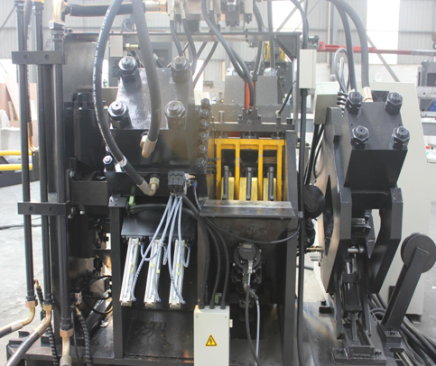
This
unit is consists of three pieces of machine body, two hydraulic pressure
punching cylinders, four die bases with upper and lower dies, and two sets of
servo systems for controlling stadia adjustment. This unit can be installed three
different standards punches on each side. Every punch matches with one gas
cylinder. The gas cylinder piston pole links a padding block, which installed
between punch poles and oil cylinder press head. It automatic chooses punch,
namely choose relevant gas cylinder to drive relevant padding block according
to the order of computer. The position of stadia is located by servo motor,
which drives ball screw to drive die base move up and down, thus to achieve the
requirement of stadia position. It can punch many rows and different diameters
holes on two wings of angle steel.
The Marking Unit:
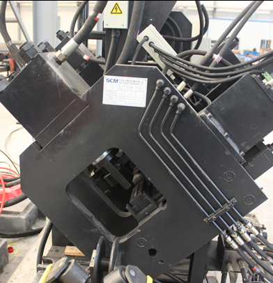
New design for type marking unit, more stable and longer life
This
unit consists of fix lathe bed, movable lathe bed, hydraulic pressure head,
four positions oil cylinders (can change four positions for character boxes)
and adjusting device. According to the order of computer, to mark on places the
drawings require. For making the mark clear and endurable, and avoiding the
angle steel abrade character heads, it adds oil cylinder of movable lathe bed
uplift and falling. For satisfying the processing scope, it adds manual
adjustment setup, which can change the position of characters to adapt
different standards angle steel.
The Shearing Unit:
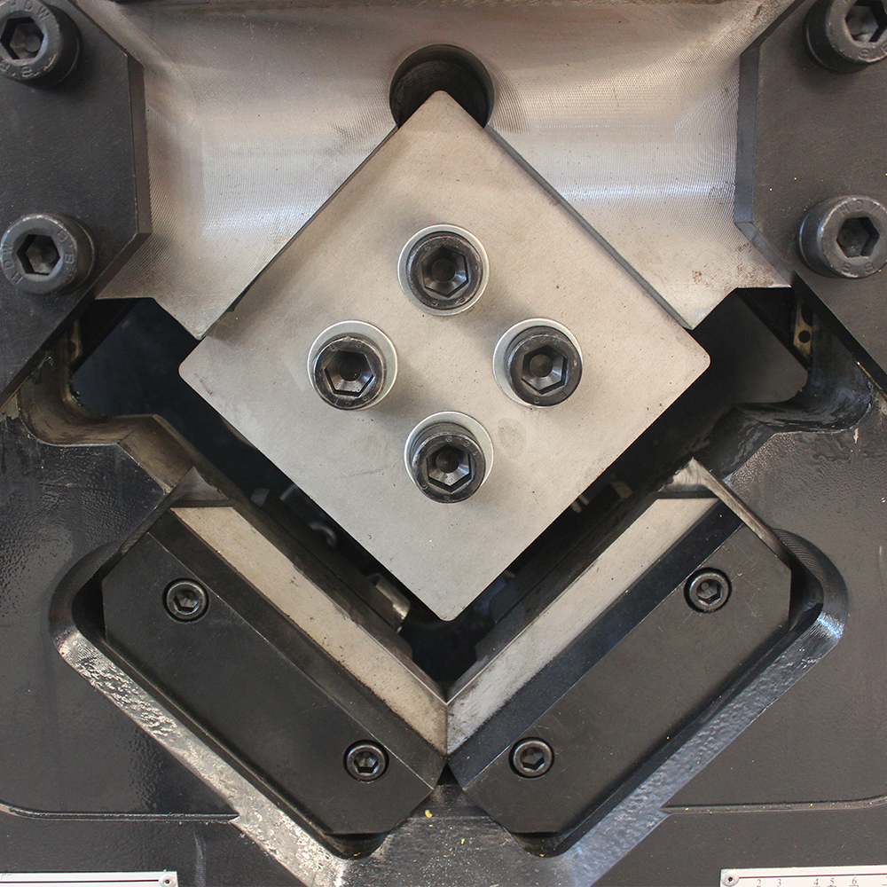
This unit consists of frame
machine body, hydraulic pressure dynamic cylinder, upper blade setup, lower blade
setup, and front bracket tank etc. The front bracket tank avoids angle steel to
strike lower blade. The lower blade setup can adjust the clearance according to
angle steel thickness to ensure the cutting quality. It cuts different
standards of angle steel, according to the order of computer.
The Feeding Conveyors:
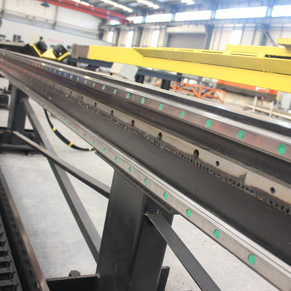
Double linear guide and detection rack for total
feeding conveyor ensure better accuracy and machine stability. Linear guide
from Taiwan HIWIN.
The NC Feeding Carriage:
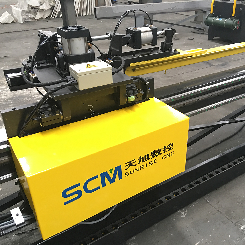 Newest NC carriage, linear guide drive, accuracy
and stability much better!
NC carriage linear guide cushion, pneumatic lift
Work Table And Overturning Rack:
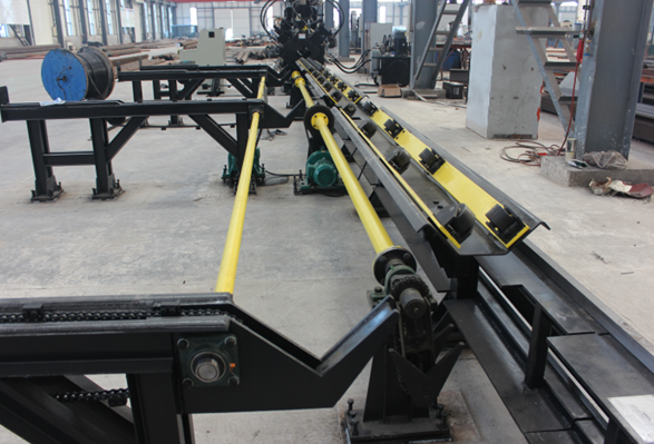
Overturn
rack for loading material automatically
Angle Punching Marking Shearing Line
Angle Punching Marking Shearing Line,Angle Connecting Plate Punching,Punching Shearing And Marking Line,CNC Angle Production Line
Shandong Sunrise CNC Machine Co., Ltd , http://www.scmcnc.com