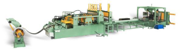
I General Layout for Transformer Corrugation Fin Production Line (fin forming, fin seam&edges welding, reinforcing rod welding, spot welding, vertical bending and tank assembling)Â Â Â
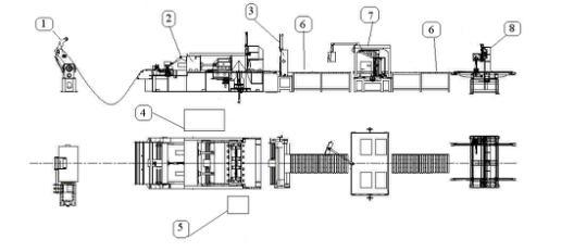
Build up of Transformer Corrugated Fin Production Line as the Drawings Shown
1. Transformer Corrugated Fin Forming Unit
1 Hydraulic Automatic Decoiler Machine       Â
2 Automatic Transformer Corrugated Fin Forming Machine
3 Â Hydraulic Plate Shearing and Hemming Machine
4 Â Hydraulic System
5 Â Electrical Control System
2. Transformer Corrugated Fin Seam Welding Unit
6 Roller Conveyor
7 Corrugated Fin Automatic Welding Machine
3. Transformer Corrugated Fin Spot Welding Unit
8 Spot Welding Machine for Fin Embossment
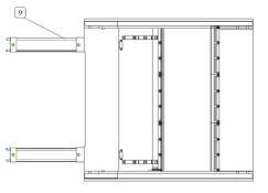
4. Transformer Corrugated Fin Vertical Bending Unit
9 Hydraulic Vertical Bending Machine
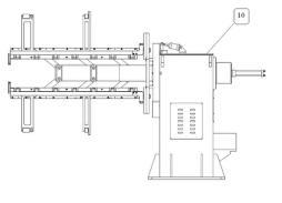
5. Corrugated Tank Assembly Unit
10 Tank Assembly Manipulator for Corrugated Tanks
General Introduction of Transformer Corrugation Fin Production Line
The corrugated fin production line is a specialized system designed for manufacturing sealed and maintenance-free transformer oil tanks. The main process involves unrolling material, forming corrugations, cutting and hemming the sheets, conveying and welding edges, adding reinforcement rods, embossing, bending, and finally assembling the tank.
Main Technical Parameters of Transformer Corrugated Fin Production Line
1. Width of corrugation: 300~1300mm
2. Thickness of steel sheet: 0.5-1.75mm
3. Length of formed sheet: >=290mm
4. Height of corrugation: 50-400mm
5. Corrugation pitch: >=40mm
6. Corrugation pitch accuracy: ±0.25mm
7. Corrugation inner gap: 6mm
8. Max. Pressure: 25MPa
9. Max. Flux: 200L/min II Equipment Description
1. Description of Necessary Machine Unit
(1) Hydraulic Automatic Decoiler Machine
1.1 Introduction
This machine has a welded steel base frame with an expandable mandrel mounted on roller bearings. It uses hydraulic systems to expand and retract the mandrel. When the steel sheet is fed automatically, a hydraulic motor on the mandrel helps in uncoiling and partially rewinding the coil. A photoelectric device with two switches detects the sheet between the decoiler and the forming unit to control the feeding process.
1.2 Parameters of Our Hydraulic Automatic Decoiler Machine
1) Hydraulic pressure: 16MPa
2) Coil inner diameter: Min 470mm, Max 520mm
3) Max. External diameter of steel coil: 1200mm
4) Coil width: Max. 1300mm
5) Coil weight: Max. 10 tons (with inclined support structure)
(2) Transformer Corrugated Fin Forming Machine
2.1 Introduction
This machine consists of a steel-welded base, 2-roll feeder, movable forming mold, and pressboards. It is used to form corrugations automatically. The process follows the theory of extrusion, controlled by a high-precision servo system. The hydraulic station supplies the necessary oil pressure. The control system is independent from the welding unit. Two quenched pressing bars are installed on both the movable and fixed pressboards to press the ends of the corrugation. These can be adjusted based on the sheet width. Reinforcement slots (embossments) can be created upon request.
2.2 Parameters of Our Transformer Corrugated Fin Forming Machine
1) Plate width: 300mm-1300mm (customizable)
2) Corrugation height: 50mm-400mm
3) Corrugation pitch: >=40mm
4) Plate thickness: 0.5mm-1.75mm
5) Forming speed: 3-4fins/min
6) Power: 28KW
7) Number of pumps: 2 (separate plunger pumps)
8) Control system: electrical, hydraulic, and control board
(3) Hydraulic Plate Shearing and Hemming Machine
3.1 Performance Features
This device is used to shear and hem corrugated steel fins. It allows easier assembly of "corrugated fin tanks" and tighter welding of different pieces. It includes lower and upper shearing blades mounted on pillars, made of tool steel for long-lasting performance. Shearing and hemming can be done manually or automatically using a feeding mechanism. The operation is hydraulically driven.
3.2 Parameters of Our Hydraulic Plate Shearing and Hemming Machine
1) Shearing width: 300mm-1300mm
2) Corrugation height: <=400mm
3) Shearing thickness: <=2.0mm
4) Shearing time: 3-5 seconds/time
5) Hemming function is optional, hemming height: 20mm (can be selected between 18mm and 25mm but must be fixed)
(4) Hydraulic System
The hydraulic system includes an oil tank, pump, motor, and valves. Key components are supplied by Rexroth, Germany.
4.1 Parameters of Our Hydraulic Station
1) Max. Pressure: 25MPa
2) Max. Flux: 200L/min
3) Pump motor power: 28KW
(5) Electrical Control System
5.1 The system includes a main control cabinet, operation console, local panels, and wiring. All relays, switches, transformers, and PLCs are housed in the main control cabinet. MITSUBISHI controllers manage the production line, while the SCHNEIDER Monitor serves as the human-machine interface. The control console features a color touch screen, buttons, and indicators. Parameters such as fin width, height, and pitch can be easily adjusted via the touch screen. Manual operations are possible through local panels.
(6) Roller Conveyor
6.1 Features
This conveyor transports sheared and hemmed corrugated sheets to the welding equipment. It uses ball bearings for smooth, non-motorized movement.
(7) Corrugated Fin Automatic Welding Machine
7.1 Introduction
This machine uses MAG welding to join the corrugation edges and reinforce rods with a 6mm-8mm round bar. It includes a conveying mechanism, torch elevation system, amplitude modulation, and a machine hand. The conveying mechanism moves the sheet to the correct welding position. The clamps and torches are driven by air cylinders and servo motors. Amplitude modulation ensures precise alignment. If there's a missing weld, the machine hand pushes the fin into place, powered by an air cylinder. Two Panasonic welders are installed in the line.
7.2 Specifications of the Welder
1) Welding speed: Vs=0.5~1 m/min
2) Welding wire feeding speed: Vd=3.4~6 m/min
3) Electric arc voltage: 15-16V
4) Welding current: 50-60A
5) Diameter of welding wire: 0.8 mm
6) Shield gas: 85% Ar + 15% CO2
7) Shield gas consumption: 15 L/min
8) Tip length of welding wire: 7~10 mm
(8) Spot Welding Machine for Fin Embossment
8.1 General Introduction
This spot welding machine increases the strength of embossments. It includes a conveyor, centering system, clamps, generators, cooling system, and a computer-controlled console.
8.2 Main Units of Corrugated Fin Spot Welding Machine
1) Conveyor
2) Centering system
3) Clamps & generators
4) Cooling system
5) Control console with computer
8.3 Parameters of Corrugated Fin Spot Welding Machine
1) With 2 spot guns
2) Total rated power: 50KVA x 2
3) Cooling system
4) HMI control system
5) Suitable fin width: 600mm-1600mm
6) Suitable fin height: >=120mm
7) Air source: Self-provided
8) Air pressure: 0.6Mpa (minimum)
(9) Hydraulic Vertical Bending Machine
9.1 This machine is used to shape four panels of a complete transformer tank. It reduces the number of welds, saving time and reducing leakage risks.
9.2 Main Units of Hydraulic Vertical Bending Machine
1) Bending system
2) Safety system for operators
3) Hydraulic unit
4) Control panel
9.3 Main Parameters of Hydraulic Vertical Bending Machine
1) Sheet thickness (max): 1.75mm
2) Panel width (max): 1300mm
3) Panel fin height: 50-400mm
4) Distance between panels (min): 60mm
5) Power: 5.5Kw
6) Hydraulic pressure: 10MPa
(10) Tank Assembly Manipulator for Corrugated Tanks
10.1 Main Features
Designed for fast and easy assembly of the top frame, tank bottom, and four corrugated panels into a complete tank.
10.2 Main Units of Tank Assembly Manipulator for Corrugated Tanks
1) Base frame
2) Hydraulic expanding head
3) Small hydraulic power pack
4) 4 sets of clamp arms
10.3 Specific Technical Data
1) Basic parameters:
Rated power: 4KW
Rated voltage: 380V
Rated pressure: 0.8MPa
Rated oil pressure: 3MPa
2) Tank inside dimensions:
Min (W) 285mm to 900 mm
Max (L) 600mm to 1500mm
2. Technical Parameters of this Transformer Corrugated Fin
| No. | Parameters | 800mm | 1300mm | 1600mm |
| 1 | Plate Width (W) | 300~800 mm | 300~1300 mm | 300~1600 mm |
| 2 | Plate Thickness (T) | 0.5~1.75mm | ||
| 3 | Corrugation Height (H) | 50~300mm | 50~400mm | |
| 4 | Corrugation Pitch (P) | >=45mm or >=40mm | ||
| 5 | Pitch Tolerance | ± 0.25mm | ||
| 6 | Hemming Height (R) | 20mm | ||
| 7 | Fin Gap (G) | 6mm | ||
A mining machine is a piece of equipment used in the mining industry to extract minerals, ores, and other geological materials from the earth. These machines are designed to dig, drill, and transport materials from one location to another in the mining process. They can be used for surface mining or underground mining, depending on the type of deposit being mined. Some common types of mining machines include Crushing Equipment, Grinding Equipment, haul trucks, drills, and Other Mining Machines. These machines are essential for efficient and productive mining operations.
Mining Machine,Jaw Crusher Machine,Hammer Crusher Machine,Mining Machine Rod Mill
Shenyang North Heavy Metallurgical Engineering Technology Co., Ltd. , https://www.nhmetallurgy.com